
Sketch to Scientific Diagram: A Step-by-Step Guide
Turn a hand-drawn sketch into a clear scientific diagram. Learn how to prepare the image, preserve its connections, write a redraw prompt, and verify the result.
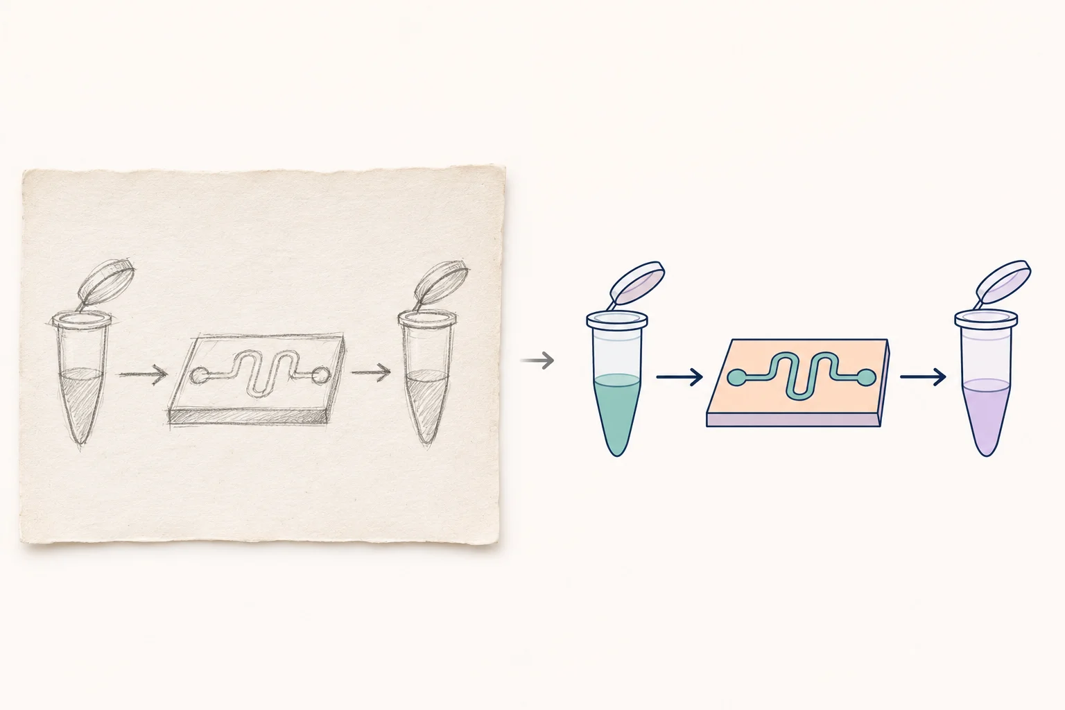
Going from sketch to scientific diagram is useful when the idea is already on paper: a pathway from a lab meeting, an apparatus drawn on a whiteboard, or a panel layout agreed with a collaborator. A sketch carries spatial information that can be tedious to describe in prose.
The goal is to improve readability while preserving the scientific structure. A cleaner drawing is only useful if it still contains the same objects, relationships, and intended meaning. The cover above is an illustrative before-and-after concept, not a recorded product output or an experimental result.
What makes a sketch a good reference?
The drawing does not need to be beautiful. It needs to be unambiguous. Boxes can stand in for instruments, circles for components, and simple lines for connections, as long as you explain what those marks mean.
A usable sketch has readable object labels, visible arrowheads, and enough space to distinguish separate branches. A rough drawing with clear connections is often more useful than a shaded illustration with unclear direction.
The Nature Reviews figure design guide also recognizes hand sketches as useful reference material. Its emphasis is on communicating the information clearly, rather than presenting polished initial artwork.
Step 1: Clean up the meaning before the image
Read through the sketch and resolve ambiguities. Does a line mean activation, transport, or simply association? Does a crossing indicate a junction? Are two similar shapes the same component appearing twice or two distinct components?
Add arrowheads and a small legend where necessary. Number the main objects if the handwriting is difficult to read. Then write a separate inventory that the generator can use alongside the reference:
| Sketch label | Intended object | Connection |
|---|---|---|
| A | Sample tube | A flows into B |
| B | Mixing chip | B flows into C |
| C | Collection tube | Endpoint; no outgoing connection |
This inventory gives you an independent record of the structure. It also helps distinguish a drawing error from an intended feature.
Step 2: Capture a readable reference image
Photograph the paper straight on, or scan it. Use even light, avoid glare, and include the entire drawing. Crop unrelated notes while keeping every meaningful connector and label. Check the image on screen before uploading it: a label that you cannot read reliably is unlikely to provide a good reference.
For whiteboards, make sure faint marker strokes are visible and reflections do not cover arrowheads. If the sketch has overlapping revisions, redraw a clean structural version rather than asking the model to guess which lines are current.
The workspace's reference uploader accepts JPG, PNG, WebP, and GIF images, with a size limit of 10 MB per image. Use a still image with enough detail to read the smallest important label. A photograph or screenshot of a sketch is an image reference, not an editable diagram source.
Step 3: Upload the sketch and state what must stay fixed
Open the generation workspace and use Add reference sketches or images. Attach the prepared sketch, then describe both the required structure and the allowed visual changes.
Redraw the attached sketch as a clean scientific diagram. Treat the sketch as the layout reference and the following list as the definitive object and connection specification. Keep exactly three objects in this left-to-right order: A, a sample tube; B, a mixing chip; C, a collection tube. Keep exactly two directed connections: A to B and B to C. Use the labels “Sample”, “Mixing chip”, and “Collection”. Improve alignment, line quality, spacing, and label readability. Use thin dark outlines, a white background, and muted teal accents. Do not add objects, branches, reverse arrows, experimental results, or scale bars. This is a schematic, not a drawing to scale.
The distinction matters: the sketch suggests placement, while the written inventory resolves meaning. If they disagree, correct the conflict before generating the image.
Step 4: Compare structure before style
Put the original sketch and the generated draft next to each other. Count the objects, count the connections, and check every direction. This review tests topology: what is connected to what. It should happen before you judge the palette or polish.
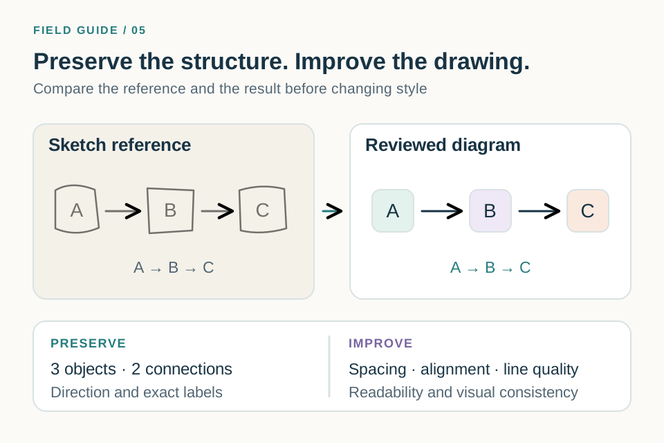
For a complex sketch, review one branch at a time. Highlight each verified connection on a copy of the reference. A missing branch is easy to overlook when the new image is visually attractive.
Next, check text. Compare abbreviations, capitalization, superscripts, and symbols with your typed label list. Do not assume that an almost-correct protein name or variable is close enough.
Step 5: Make targeted corrections
When the output differs from the sketch, say exactly what changed and what to restore:
Keep the current visual style and the three existing objects. Remove the extra connection from A to C. The only connections must be A to B and B to C. Preserve the left-to-right order and the three labels.
Use the selected draft as a reference when refining its appearance. Keep the original sketch available as the structural check. A request to preserve the layout does not guarantee that every component will remain unchanged, so repeat the comparison after each revision.
If a dense sketch repeatedly produces missing or added branches, divide it into smaller panels or finish the connections with an editor that supports individual objects. For detailed pathways, the mechanism diagram guide explains how to prepare a relationship inventory.
Troubleshooting common redraw problems
| Problem | Likely ambiguity to resolve | Practical fix |
|---|---|---|
| Handwriting becomes incorrect text | Labels are hard to read | Supply an exact typed label list |
| Crossing lines become a junction | The connection is unclear | Mark the crossing and describe it explicitly |
| An arrow changes direction | The arrowhead is faint or obscured | Redraw the arrowhead and list source and target |
| Extra components appear | The prompt leaves gaps open | State the exact object count and exclusions |
| Relative positions drift | Layout constraints are implicit | Describe regions, order, and fixed groupings |
Frequently asked questions
Can I use a very rough sketch?
Yes, if its meaning is clear. Simple boxes and arrows are enough for many workflows. Add text instructions wherever the sketch leaves room for interpretation.
Will the output preserve the sketch exactly?
An image-generation workflow may change shapes, spacing, labels, or connections. Use the sketch as a reference, specify the invariants in text, and verify the result. Exact preservation needs explicit checking.
Can I edit each component after generation?
An image output does not automatically contain independently editable components. If you need to move individual nodes or change text repeatedly, plan a finishing step with an appropriate editor and verify any conversion before relying on it.
What files should I keep?
Save the original sketch, the clean reference image, the typed connection inventory, the prompt, and the reviewed output. Together they make later revisions easier to understand.
Turn your next lab sketch into a draft in the figure generation workspace. If you are starting without a drawing, the AI scientific figure generator guide explains how to build the same brief from text.